
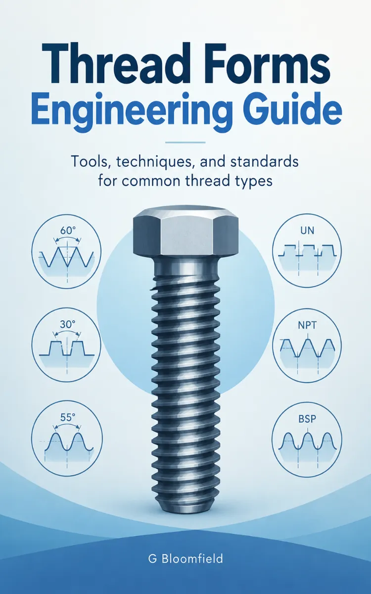

Read the first chapter
The whole of chapter one, free. About 4 min. Turn the pages with the arrows, your keyboard, or a swipe.
Chapter 1
Thread Basics and Terminology
Why Thread Terms Matter
What happens when a bolt appears to fit, yet strips under load or binds before the joint closes? The answer usually lies in thread geometry, fit, or identification - not in the wrench.
A thread specification defines more than diameter. It controls pitch, flank angle, crest and root shape, pitch diameter, and tolerance. These features determine how parts assemble, share load, resist wear, and seal. A correct term prevents an incorrect tool, gauge, or replacement fastener.
After this chapter, you can identify the working dimensions of a thread, distinguish clearance from interference fit, and predict how geometry affects strength and function. The Thread Map Primer provides the reference method: identify the thread, map its geometry, then verify its fit.
The Thread Map Primer
Use this map before cutting, measuring, or selecting a mating part:
| Map item | Meaning | Why it matters | |---|---|---| | Major diameter | Largest diameter over external crests or internal thread crests | Identifies nominal size | | Minor diameter | Smallest diameter at the root region | Indicates material remaining and clearance | | Pitch | Axial distance between matching points on adjacent threads | Determines lead and engagement | | Lead | Axial travel in one revolution | Equals pitch for a single-start thread | | Flank angle | Angle between a flank and the thread centerline reference | Controls load direction | | Pitch diameter | Imaginary diameter where thread thickness equals groove width | Governs fit | | Crest and root | Top and bottom of the thread profile | Affect clearance, stress, and damage resistance |
For example, a single-start thread with a 1.5 millimetre pitch advances 1.5 millimetres per revolution. A multi-start thread advances by its pitch multiplied by the number of starts.
1. Identify the nominal system. Record diameter, pitch or threads per inch, and form, such as Metric, Unified National Coarse (UNC), Unified National Fine (UNF), British Standard Whitworth (BSW), or British Standard Fine (BSF). 2. Map the profile. Check flank angle, crest form, and root radius. A Whitworth profile does not mate correctly with a Unified profile of similar diameter and pitch. 3. Map the fit. Compare pitch diameter and tolerance class, not only major diameter. 4. Map the load path. Examine engagement length, flank contact, and root section before approving the joint.
Ask yourself: does the measured pitch and profile match the drawing, or does only the outside diameter match?
Applying the Map to a Threaded Joint
A steel stud measures 12.00 millimetres at the major diameter and has a 1.75 millimetre pitch. The drawing calls for a Metric coarse thread with a 6g external tolerance and a matching 6H internal thread.
1. Confirm identity. Use a pitch gauge and verify 1.75 millimetres; do not substitute a visually similar Unified thread. 2. Check form. Inspect the crest and root with the correct gauge or optical comparator. The expected outcome is full flank contact without crest interference. 3. Check fit. Measure the stud with a three-wire method or approved external-thread gauge, then check the tapped hole with a 6H plug gauge. The gauge should pass through the GO section and stop at the NO-GO section. 4. Check function. Assemble the parts by hand for several turns before applying a wrench. Correct parts should run smoothly and seat at the specified shoulder without forced tightening. 5. Assess strength. Confirm sufficient engagement and inspect the minor diameter. A deep root cut or short engagement reduces the available shear area.
Quick checklist
• Confirm diameter and pitch. - Confirm thread standard and flank angle. - Verify pitch diameter and tolerance class. - Check crest, root, and flank contact. - Use matching GO and NO-GO gauges. - Assemble by hand before applying torque.
The expected result is a joint that seats fully, carries load through the flanks, and avoids crest damage.
Common Errors and Edge Cases
Matching diameter but not thread form A 12 millimetre thread can still be wrong if its pitch or profile differs. Do this: verify pitch and standard with gauges. Not this: force the nut because the first turn engages.
Confusing pitch with lead A multi-start thread may advance several times its pitch per revolution. Do this: calculate lead as pitch multiplied by starts. Not this: infer lead from outside appearance.
Ignoring pitch diameter Major diameter alone cannot establish fit. Excessive clearance reduces flank contact; insufficient clearance causes seizure. Do this: measure or gauge pitch diameter to the specified tolerance. Not this: approve a thread from caliper readings alone.
Thread geometry converts tightening torque into axial clamping force. Accurate identification and fit verification protect that load path before cutting tools or assembly torque enter the process.
End of chapter one. 7 more chapters in the full book.
Swipe or use the arrows to turn the page

What's inside: 8 chapters
- 1. Thread Basics and Terminology
- 2. BSW and UNF/UNC Thread Standards
- 3. Cycle Threads: BA and BSF
- 4. Metric Thread Forms and Fits
- 5. Tooling for Thread Cutting and Tapping
- 6. Single-Point Threading Setup and Feeds
- 7. Tapping Techniques and Chip Control
- 8. Measuring Thread Quality and Troubleshooting
About this book
"Thread Forms Engineering Guide" is a how-to guide book by G Bloomfield with 8 chapters and approximately 6,032 words. Thread forms, standards, and methods for cutting and measuring threads.
This book was created using Inkfluence AI, an AI-powered book generation platform that helps authors write, design, and publish complete books. It was made with the AI Ebook Generator.
Frequently Asked Questions
What is "Thread Forms Engineering Guide" about?
Thread forms, standards, and methods for cutting and measuring threads
How many chapters are in "Thread Forms Engineering Guide"?
The book contains 8 chapters and approximately 6,032 words. Topics covered include Thread Basics and Terminology, BSW and UNF/UNC Thread Standards, Cycle Threads: BA and BSF, Metric Thread Forms and Fits, and more.
Who wrote "Thread Forms Engineering Guide"?
This book was written by G Bloomfield and created using Inkfluence AI, an AI book generation platform that helps authors write, design, and publish books.
How can I create a similar how-to guide book?
You can create your own how-to guide book using Inkfluence AI. Describe your idea, choose your style, and the AI writes the full book for you. It's free to start.
Write your own how-to guide book with AI
Describe your idea and Inkfluence writes the whole thing. Free to start.
Start writingCreated with Inkfluence AI


