
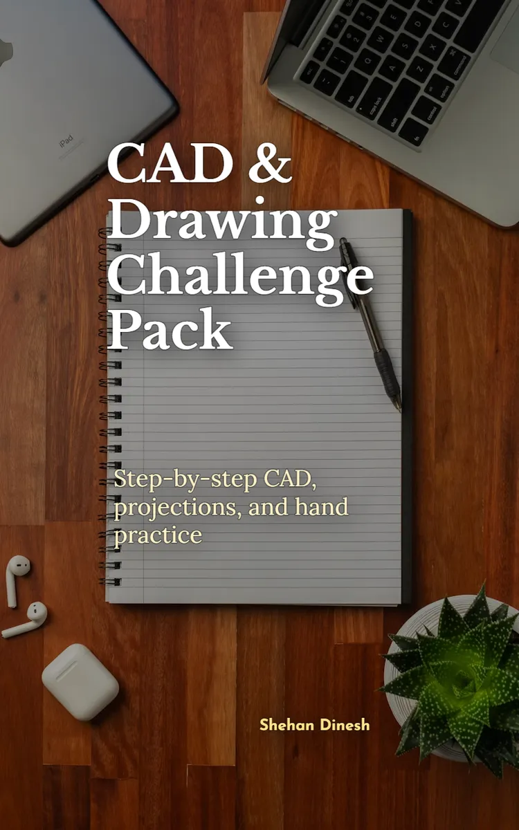
Read the first chapter
The whole of chapter one, free. About 8 min. Turn the pages with the arrows, your keyboard, or a swipe.
Chapter 1
CAD Sketching Basics and Constraints
Why a Fully Defined Sketch Matters
Can you change one dimension in a CAD sketch without the entire profile shifting unpredictably? A fully defined sketch gives you that control. It fixes the profile’s shape, size, and position so the drawing behaves like a reliable mechanical part instead of a collection of loose lines.
A two-dimensional profile forms the starting shape for many CAD parts. You can later extrude it into a solid, revolve it around an axis, or use it to create a cut. If the sketch contains gaps, duplicate dimensions, or uncontrolled geometry, later features may fail or produce the wrong shape. Dimensioning and constraints solve these problems by telling the CAD system exactly how the lines and curves relate.
The goal is not to add as many dimensions as possible. The goal is to define only the information the profile needs. You will learn to create connected geometry, apply geometric constraints, add driving dimensions, and check the remaining degrees of freedom. You will also use the Sketch-Define-Verify Loop to find problems before they affect later features.
A practical takeaway: treat every sketch as a controlled set of relationships, not just a picture on the screen. Before moving on, ask yourself whether the profile would remain correct if you changed its main size.
The Sketch-Define-Verify Loop
Most CAD programs provide similar sketch tools. The names may differ slightly, but you will usually find a line tool, arc or circle tool, trim tool, dimension tool, and constraint tools. A geometric constraint controls a relationship, such as horizontal, vertical, parallel, tangent, equal, or concentric. A dimensional constraint controls a value, such as a length, angle, radius, or diameter.
Use the Sketch-Define-Verify Loop in this order:
1. Sketch the basic geometry. Draw the rough profile with lines, arcs, and circles. Do not worry about exact size yet. Focus on the correct shape and make each endpoint meet the next endpoint. 2. Define the relationships. Apply geometric constraints such as horizontal, vertical, coincident, tangent, and equal. These relationships control how the geometry behaves when you edit a dimension. 3. Add dimensions. Enter the required lengths, angles, radii, and positions. Add dimensions that describe the design, not measurements that merely repeat other information. 4. Verify the sketch. Check the solver message, remaining degrees of freedom, and the profile’s behavior. Drag an underdefined point if your CAD program allows it. A fully defined profile should not move. 5. Repeat only where needed. If the sketch still moves, add the missing relationship or dimension. If the CAD program reports an overdefined sketch, remove the duplicate or conflicting condition.
Start geometry near the origin, which is the fixed reference point at the center of the sketch plane. For a symmetrical bracket, place its centerline on the vertical axis. This choice reduces the number of dimensions needed and keeps the part centered when you change its width. A coincident constraint makes two points occupy the same location. Apply it when you need to join endpoints, because lines that only appear to touch may still contain a small gap.
Next, apply shape constraints before size dimensions. For example, select the two side edges of a plate and apply an equal constraint if they must match. Select a line and the horizontal axis to apply a horizontal constraint. For a rounded corner, make the arc tangent to both adjoining lines. Tangency keeps the transition smooth; a visual touch without tangency can create a sharp change in direction.
Dimensions should describe the design in a clear order. Set the overall width and height first, then locate holes, slots, or steps from a known edge or centerline. Use a diameter dimension for a full circle and a radius dimension for an arc. Avoid dimensioning the same condition twice. For example, do not define a rectangle with both its width and the distance between two edges if those values describe the same width. That can create an overdefined sketch.
Ask yourself three questions during verification: What can still move? Which dimension controls the main size? Does the profile stay connected when I change that dimension? If the answer to the first question is “nothing,” the sketch is fully defined. If the profile turns red or refuses a new dimension, remove the conflicting condition instead of forcing another value.
The practical takeaway is simple: rough geometry establishes the shape, constraints establish the relationships, dimensions establish the size, and verification proves that the sketch can support the next CAD feature.
Applying the Loop to a Mounting Plate Profile
Use a simple mounting plate as a complete practice task. Create a 100 millimeter wide by 60 millimeter high plate with four corner holes. Give the plate 10 millimeter corner radii and place each hole 15 millimeters from the nearest side. Use 8 millimeter diameter holes. The expected result is a fixed, symmetrical profile with four equal holes.
1. Create a new sketch on the front plane. Select the sketch command and choose the front or XY plane, depending on your CAD program. The front plane gives you a flat view for the 2D profile. 2. Draw the outer rectangle. Use the rectangle tool and place its lower-left corner near the origin. Draw the opposite corner above and to the right. The rough rectangle does not need exact dimensions. 3. Constrain the rectangle. Apply horizontal constraints to the top and bottom edges and vertical constraints to the two side edges. Apply coincident constraints at the four corners if the rectangle tool did not create them automatically. 4. Center the plate. Use the origin as the center reference, or place the lower-left corner at the origin if your drawing requires that layout. Choose one method before adding dimensions, because changing the reference later can make the sketch harder to control. 5. Add the main dimensions. Apply a horizontal dimension of 100 mm and a vertical dimension of 60 mm. The rectangle should now have the correct size, but it may still move if you did not anchor its position. 6. Create the corner rounds. Use the fillet tool on each corner and enter a radius of 10 mm. Check that each arc connects smoothly to both adjoining edges. 7. Add the first hole. Draw a circle near the lower-left corner. Apply a diameter dimension of 8 mm. Add horizontal and vertical dimensions from the hole center to the two nearby outer edges: 15 mm in each direction. 8. Pattern the remaining holes. Use a rectangular pattern tool if available, or create three more circles. Apply equal constraints so every circle matches the first hole. If you create the circles manually, dimension the center locations from the plate edges or centerlines. 9. Check the solver status. Look for an “underdefined” message or remaining degrees of freedom. If the holes move together, confirm that the equal and location constraints control the complete pattern. If one hole moves alone, add its missing location constraint. 10. Test the profile. Change the width from 100 mm to 120 mm. The plate should grow in width while the holes remain 15 mm from their assigned edges. Change the hole diameter from 8 mm to 10 mm. All four holes should update together.
A fully defined sketch should now show no uncontrolled movement. The outer profile should remain connected, each corner should retain a 10 mm radius, and the holes should keep their intended spacing. Save the sketch with a clear name such as Mounting_Plate_Profile, because a useful name helps you find the correct sketch when the model contains several features.
Quick checklist
• Draw the complete outer boundary before adding small details. - Confirm that every adjoining endpoint has a coincident connection. - Apply horizontal, vertical, equal, and tangent constraints where the design requires them. - Use 100 mm and 60 mm as the overall plate dimensions. - Use 10 mm for each corner radius. - Use 8 mm diameter for each hole. - Locate each hole center 15 mm from the required edges. - Check that the sketch reports no remaining movement. - Change one main dimension and confirm that the profile updates correctly.
The practical test matters more than the color of the sketch lines. A profile that changes correctly under editing is easier to reuse and safer to turn into a solid feature.
Common Constraint Problems and Their Fixes
The sketch looks closed, but the profile has a gap
A tiny gap between two endpoints can prevent an extrusion or create an open contour. Zoom in on every corner, especially after trimming or moving geometry. Select the two endpoints and apply a coincident constraint. If the endpoints sit close together but do not share one point, delete the affected line and redraw it using the existing endpoint.
Do this: Use endpoint selection and a coincident constraint, then check the closed-profile tool.
Not this: Trust the screen appearance at normal zoom and assume touching lines form a closed boundary.
The sketch becomes overdefined
An overdefined sketch contains more conditions than the geometry can satisfy. For example, a rectangle may already have a horizontal constraint and a fixed width, but you may add another dimension that repeats the same width. The CAD solver then reports a conflict.
Do this: Read the conflict list, suppress or delete the duplicate constraint, and keep the dimension that best describes the design intent.
Not this: Add more constraints to force the sketch into place. Extra constraints make future edits harder and can create new conflicts.
The profile remains underdefined
Underdefined geometry still has degrees of freedom, meaning it can move, rotate, or change size. A circle with a diameter but no center location can still move anywhere on the sketch. A rectangle with width and height but no position can slide across the plane.
Do this: Identify the movement first. Add a center location, edge distance, symmetry constraint, or relation to the origin that controls that movement.
Not this: Use a fixed or lock command on every loose element without understanding why it moves. A fixed element may hide missing design relationships and make later changes difficult.
A reliable final check combines the solver message with a controlled edit. Change the 100 mm plate width to 120 mm, then restore it. If the corners, holes, and center references respond as intended, your dimensions and constraints support the design. If an unrelated feature jumps, return to the Sketch-Define-Verify Loop and inspect the relationship that should control it.
A fully defined sketch is ready for the next drawing task because its intent remains clear: connected geometry forms the profile, constraints control its behavior, and dimensions give it measurable size. That same discipline supports accurate projections, clean mechanical drawings, and confident hand-sketch practice throughout the rest of the pack.
End of chapter one. 4 more chapters in the full book.
Swipe or use the arrows to turn the page
What's inside: 5 chapters
- 1. CAD Sketching Basics and Constraints
- 2. Orthographic Views with 3rd Angle
- 3. Dimensioning Rules for Mechanical Drawings
- 4. Section Views and Hatching Practice
- 5. Hand Drawing Practice for CAD Accuracy
About this book
"CAD & Drawing Challenge Pack" is a how-to guide book by Shehan Dinesh with 5 chapters and approximately 9,123 words. Mechanical engineering CAD drawing, projections, and hand sketching practice.
This book was created using Inkfluence AI, an AI-powered book generation platform that helps authors write, design, and publish complete books. It was made with the AI Ebook Generator.
Frequently Asked Questions
What is "CAD & Drawing Challenge Pack" about?
Mechanical engineering CAD drawing, projections, and hand sketching practice
How many chapters are in "CAD & Drawing Challenge Pack"?
The book contains 5 chapters and approximately 9,123 words. Topics covered include CAD Sketching Basics and Constraints, Orthographic Views with 3rd Angle, Dimensioning Rules for Mechanical Drawings, Section Views and Hatching Practice, and more.
Who wrote "CAD & Drawing Challenge Pack"?
This book was written by Shehan Dinesh and created using Inkfluence AI, an AI book generation platform that helps authors write, design, and publish books.
How can I create a similar how-to guide book?
You can create your own how-to guide book using Inkfluence AI. Describe your idea, choose your style, and the AI writes the full book for you. It's free to start.
Write your own how-to guide book with AI
Describe your idea and Inkfluence writes the whole thing. Free to start.
Start writingCreated with Inkfluence AI


